
Getting Started
This guide covers the basics of the SpicePad circuit editor — placing components, drawing wires, adding text, and managing your schematic.
The Toolbar

The toolbar across the top of the editor gives you access to the main tools and actions:
| Button | Shortcut | Description |
|---|---|---|
| Select | S | Default mode. Click to select components and wires, or drag to marquee-select multiple items. |
| Probe | P | Place voltage or current probes on wires for simulation. |
| Delete | D | Click any component, wire, probe, or text to remove it. |
| New | Clear the canvas and start a new circuit. | |
| Open | Load a previously saved circuit file. | |
| Save | Save the current circuit to a file. | |
| Netlist | View or export the SPICE netlist for the circuit. |
Wire mode (W) and Text mode (T) are activated with keyboard shortcuts rather than toolbar buttons.
The Component Panel
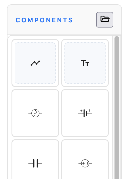
The left sidebar lists all available components. The first two tiles — Wire and Text — are special tools for drawing wires and placing text annotations. The remaining tiles are circuit components (resistors, capacitors, voltage sources, etc.).
To place a component:
- Click a component in the panel to select it. A ghost preview will follow your cursor.
- Press R to rotate the preview before placing.
- Click on the canvas to place the component. It will snap to the grid automatically.
Each component is auto-assigned a designator (R1, C1, V1, etc.) and a default value. Double-click any placed component to open the editor and change its designator, value, or SPICE model.
Wires & Text
Drawing Wires
Press W or click the Wire tile in the component panel to enter wire mode.
- Click to start a wire. Clicking on an existing wire splits it and starts a new connection from that point.
- Move the mouse to route the wire — wires are drawn with orthogonal (L-shaped) bends that follow your cursor direction.
- Click to place intermediate waypoints.
- Double-click or press Escape to finish the wire.
Junctions are created automatically where wires cross or connect.
Adding Text
Press T or click the Text tile to enter text mode, then click on the canvas to place a text cursor. Type your annotation and press Enter to confirm, or Escape to cancel. Click on existing text in text mode to edit it in place.
Dragging Components & Labels
In Select mode (S), click and drag any component to reposition it. Wires connected to its pins will stretch to stay connected.
You can also drag wire nodes and segments to reshape your routing.
To select multiple items, click and drag from empty space to draw a selection rectangle. All enclosed components and wires are selected and can be moved together as a group.
Component labels (designator and value) can be dragged independently to reposition them around the component.
Deleting Components
There are two ways to delete items:
- Delete tool — press D or click the delete button in the toolbar, then click the item you want to remove.
- Selection delete — in Select mode, select one or more items, then press Delete or Backspace.
When you delete a component or wire, any orphaned wire nodes are automatically cleaned up.
Putting It All Together
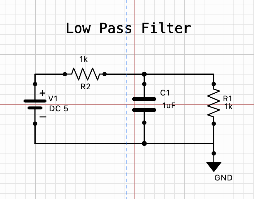
The screenshot above shows a simple low-pass filter built with SpicePad. Components are wired together, labels are positioned for readability, and a title is added with the text tool.
Keyboard Shortcuts Reference
| Shortcut | Action |
|---|---|
| S | Select mode |
| W | Wire mode |
| T | Text mode |
| D | Delete mode |
| P | Probe mode |
| R | Rotate component / probe |
| C | Place selected component |
| ⌘/Ctrl + Z | Undo |
| ⌘/Ctrl + Shift + Z | Redo |
| ⌘/Ctrl + Enter | Run simulation |
| Escape | Exit current mode / clear selection |
| Delete / Backspace | Delete selected items |